I.B.
+ M.A. DE LANDE LONG
SOFTWARE + CONSULTANCY
Spacecraft Packet Telecommand Architecture
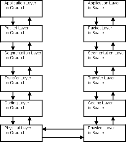
The diagram shows the layers in the Packet Telecommand architecture at the sending end (ground) and
receiving end (space).
It is based on the architecture shown in the ESA Packet Telecommand Standard (1992) and in the
original CCSDS recommendations for telecommand.
Our Telecommand Encoder Shell and Telecommand Decoder Shell
implement the Segmentation, Transfer and Coding Layers on ground and in space.
In the current CCSDS recommendations, the architecture is covered by a number of different protocols:
-
Packet Layer - Space Packet Protocol
-
Segmentation Layer and Transfer Layer - TC Space Data Link Protocol
-
Coding Layer and parts of the Physical Layer - TC Synchronization and Channel Coding
The protocols are defined in the current CCSDS recommendations, which also show the relationships
to the standard layers of the OSI model.
There have been changes to the names of the layers:
- the Packetization Layer, or Packet Layer, is not described as a layer or sublayer in the current recommendations
- the Segmentation Layer is now called the Segmentation Sublayer
- the Transfer Layer is now called the Transfer Sublayer
- the Coding Layer is now called the Synchronization and Channel Coding Sublayer
TC Encoder Shell
TC Decoder Shell
TC Standards and Recommendations
TC Features
HOME
PRODUCTS
CONTACT
Online link to home page http://www.delandelong.com
List of abbreviations
Copyright © 1997-2008
by I B + M A de Lande Long